- 7 Segment Display Using Common Anode Verilog Projects
- 7 Segment Display Using Common Anode Verilog And System
OVERVIEW
The basys 3 fpga comes with 4 different 7 segment display with different anode but common cathodes to light us the display led. I am unable to display two different values at the displays. Eventually, I need to build a 0000 to 9999 counter using all 4 different 7 display segments, so using hex counting will not work for me.
Interfacing with FPGA: The board we are using in this tutorial is Xilinx X-SP6-X9 which contains on board 8 seven-segment displays as shown. This board contains 4 seven-segment displays in 2 packages. For each package contains 4 seven segment displays having 4 common anode points and 8 segments including dot point. 7 segment MUX Not showing the wanted digit. I want to show digits in the range from 0.0 to 99.5, step 0.5, on a 7 segment display. I have 3 seven segment displays available, they are connected in a MUX, so I have 7 pins for segments and 3 select pins for choosing the digits. In the attached Verilog code I made a display of specific.
This tutorial shows how to control 7-segment on Nexys3. Two method will be introduced: software and hardware. Software method will generate 7-segment control signals with PicoBlaze while hardware method will focus on controlling 7-segment with Verilog.
STEP 1: Introduction of Seven-Segment
The Nexys3 board contains a four-digit common anode seven-segment LED display. Each of the four digits is composed of seven segments arranged in a 'figure 8' pattern, with an LED embedded in each segment as the picture shows.
Neo geo bios rom (neogeo.zip). There are two types of LED 7-segment display: Common Cathode (CC) and Common Anode (CA). In CA, all the anode connections of the LED segments are joined together to logic '1' as the picture shows. The individual segments are illuminated by applying a ground, logic '0' or 'LOW' signal via a suitable current limiting resistor to the Cathode of the specific segment (a-g). More details for 7-segment display please refers to REF [2].

To drive CA seven-segment, put '0' to I/O port to light LED. For example, if you want to display 1 as the picture shows, the output port for abcdefg is 1001111.

To drive CA seven-segment, put '0' to I/O port to light LED. For example, if you want to display 1 as the picture shows, the output port for abcdefg is 1001111.
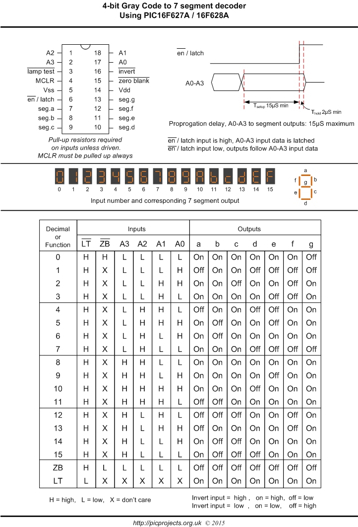
The truth table is for displaying 1 to 9 with CA 7-segment.
7 Segment Display Using Common Anode Verilog Projects
STEP 2: Display 4-digit Number in Software
Nexys3 provides four-digit seven-segment, namely, 4 digits can display at the same time (see picture 1 in step 1). As we said before, each seven-segment needs 8-bit data to fully display, which means 4x8=32-bit are needed to display 4 seven-segment. We do not have so much I/O pins for seven-segment. To overcome this defect, Nexys3 share the same data bus (8 LEDs, from A to DP as previous table shows) for 4 digit seven-segment. Therefore, it's not easy to display 4 digits at the same time. To make sharing bus work, Nexys3 provides four triodes to enable each seven-segment. To display multi-digits instead of only one digit, you will need to enable each triode one by one and send corresponding data to CA to DP port. But pay attention, delay for short time after enable a triode will need to guarantee triode works correctly. Because data for displaying numbers has no regular pattern, you cannot calculate them but can use look-up table.
Now let's do some fun thing with seven-segment! Suppose we want to read 8-bit input from slide switches and split 8-bit input into two 4-bit numbers, add them and display numbers and add result on seven-segment in hex. Following picture shows the flow chart in assembly way.
STEP 3: Display Four Digit Numbers in Verilog
Previous step discusses how to display seven-segment with software, this part will focus on displaying seven-segment in Verilog. We will use the same task to illustrate how to control seven-segment in Verilog code. Adder result will be output using out_port[7:0], using bcd_display moduletransferring 8-bit result into decimal and display on seven-segment in Nexys3 as the picture shows.
The code in this step is here. Note: Code for Decode data into decimal comes from REF [3], code for BCD_Display module based on [3]
REF
[1] https://reference.digilentinc.com/reference/programmable-logic/nexys-3/reference-manual
[2] https://www.electronics-tutorials.ws/blog/7-segment-display-tutorial.html
7 Segment Display Using Common Anode Verilog And System
[3] http://bits.usc.edu/ee209/labs.html

